Overall design description
Our design is focused on providing a safe and efficient transportation system, which will actually attract passengers with its simplicity, familiarity and user friendliness.
In the process of designing our solutions concerning Hyperloop system we based on using technologies which already exist, are being introduced or have potential for further development. The initial goal from which we started was encouraging people to use this new transportation system along with introducing technologies which do not seem to be an obvious solution, but add some real value to the design.
Our priority is to show that travelling by Hyperloop is safe, economically viable and that it will trigger off a breakthrough in worldwide transportation.

HyperLodz design
Pod structure
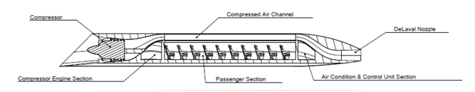
Division into sections
HyperLodz Team Pod is able to transport 30 passengers aboard. The capsule is 23 m long, 2.8m wide and over 2.5 m high. The total pod mass is equal to 25 000 kg.
Section view

Pod vertical cross-section
Propulsion
Compressor
The compressor is designed to push the air from front of the pod in order to avoid so called syringe effect, which would increase aerodynamic losses considerably. It is presented below.

Model of the compressor inlet
Furthermore, the nozzle outlet is optimized to give maximum thrust.

Graph of Thrust vs. Mach number at the nozzle outlet
Levitation and maneuvering
Arx Pax engines
Magnetic Field Architecture
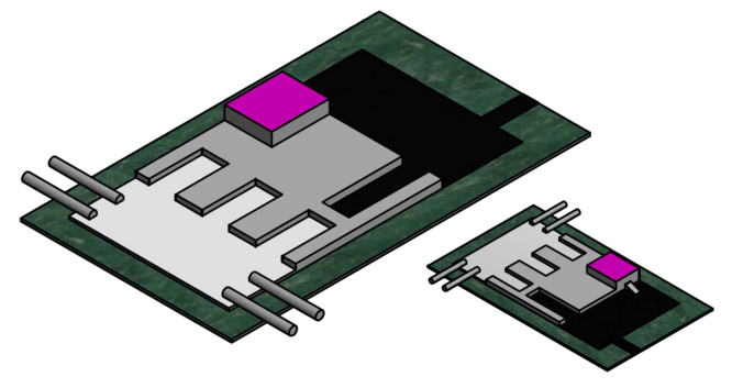
HyperLodz Team decided on using MFA technology provided by Arx Pax for levitating the pod. There are plenty of reasons to use this solution. MFA™ (Magnetic Field Architecture) is a new and relatively cheap technology. It provides more capabilities than traditional maglev or air bearings.
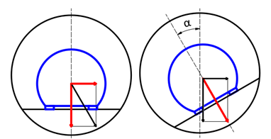
A hover engine use electromagnetic energy and is based on Lenz’s Law. Primary changing magnetic field generated by the engine creates eddy currents. The eddy currents generate a magnetic field of their own, which reflects the primary field resulting in levitation if the energy is focused downward (figure below).

Basic explanation of hover engine working principle (1)
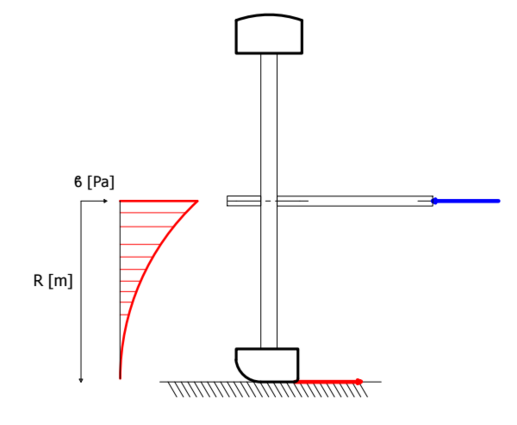
To generate propulsion/braking force, hover engine should be actuated. Than the lift vector is converted into propulsion. The lift provided by the hover engine can diminish depending of the magnitude of actuation. In general, thrust depends on tilt orientation of the engine relative to the hover surface. The direction of the thrust is parallel to the axis of tilt (Figure below)

- Generation of a directional force (2)
Aerodynamics
Shape of the capsule
External geometry of the capsule has been designed in such a way to cause as little aerodynamic drag as possible.

Rear of the capsule
Rear of the capsule is shaped in a way that resembles a droplet in a free fall. This can be regarded as an optimum trade off between stability of the capsule (magnetic suspension should have constant clearance above the track) and aerodynamics.

Front of the capsule
The very tip of the end of the capsule is an outlet of the de Laval nozzle. It is placed in the center providing steady thrust which compensate for the viscous drag.
Numerical simulations of external aerodynamics
In order to examine the flow around the Pod we’ve decided to use the Ansys software to carry on the simulation. CFX was used and the boundary conditions have been set that were adequate to the real ones.The figure presented below gives an overview on the Mach number in the flow around and partially in the Pod.

Mach number in the tube
Safety systems
Emergency scenarios
Due to some emergencies that may occur during the travel, safety procedures were designed to support the system. The following emergency scenarios have been defined:
- Power outage (pod and tube)
If power outage occurs, there are batteries placed in separated anti-fire chambers with low pressure and low oxygen content. Failure of one batteries’ set does not cause failure of the whole system. In such case, pod may stop at the by-pass point where the failed section is replaced which allows to finish the journey safely. Total power outage is not assumed as the batteries are divided into subsections. Additional trolleys stationing in the by-pass tubes can push the pod to the next by-pass or pull it back to the previous one.
- Tube depressurization
As tube depressurization may occur, the main control system constantly monitors the level of pressure in the tube. When a minor leak is detected, capsule’s velocity automatically decreases and further control of the leakage area is performed to ensure that there is no threat to passengers’ safety. In case of severe leak, which may suggest tube destruction, the sensor control system automatically decides to change direction of a capsule to a safety by-pass tube.
- Capsule depressurization
Each capsule is equipped with a pressure sensors system which connects with global control system. In case of a leak, pod is directed to a bypass for inspection while people may board additional pod which is in the bypass. During pressure drop, oxygen masks are available for passengers to ensure the breathing conditions and safety. The vacuum influence on human body has not been examined in available researches, however, every 3 to 5 minutes by-pass exit is available. Therefore human can withstand the pressure difference without significant medical conditions during the time needed to access the exit.
- Fire
In case of a fire, each capsule has smoke detectors in both passengers’ and machine elements’ part. After sensing the smoke, each pod is moved to the nearest bypass tube or exit.
When the smoke is detected in part with machine elements, the fire area is rapidly depressurized and repressurized. As a result of lack of oxygen, the fire is extinguished. The batteries are divided into 16 parts with 0.25 inch wide with aluminums armed plate to decrease the speed of fire spread or explosion. The temperature monitoring system is implemented therefore when batteries are heated up, the system unplugs them from the circuit.
In case of fire in part with passengers, every capsule has a fire extinguishing system on board. Self-extinguishing materials and PBDE are used in the capsule therefore the possibility of fire is reduced. Fire extinguishers with higher concentration of non-flammable materials such as used in space stations are placed in the capsule.
By-pass Tube
In case of a random event which implies a need for an instantaneous leaving the tube, we have created the ByPass. It is a mid-station. Located next to a freeway makes it possible to react quickly in case of a breakdown or in a life-threatening situation. When whole the system is broken the passengers may be transported on a freeway to the final destination.
The ByPass idea may be a base to creating new mid-stations which will be required after building another Hyperloop locations and further project development.
The ByPass description presented below is divided into following sections:
- A – Exit
- B – Air lock
- C – Station
- D – Carriage
Below, the detailed description of each part is presented:
A – Exit
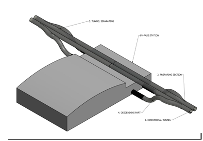
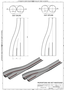
In a situation demanding leaving the tube, the pod is being prepared to enter the ByPass station. It takes place in a special tunnel which segments are presented below.
Exit scheme

Overview of the ByPass exit
A1 – Directional tunnel.
A2 – Section preparing the pod to enter the ByPass. Pods are being separated so as to ensure the repeatability, universality and modularity – the tube is being divided into two. The rail comes out and the pod enters the ByPass.
A3 – Tubes separation. The leaving pod starts to move away from the primal path, entering the ByPass. Separating segments are 200 m long (it is due to the curvature of the rail).
A4- The track lowers its vertical position. This part will be up to 2 km long which will allow the pod to brake with 3G acceleration. The segment ends with the pressure chamber.
B – Air-lock
In order to equalize the pressure at the inside of the tunnel, the pod passes through the equalizing air-lock. It is located at all the entries and exits of each station. The pod should enter the air-lock with the maneuvering speed and then it should stop inside. After equalizing the pressure, the pod leaves the air-lock. It should be a one-stage air-lock, working in the range from 0.1 to 1 bars.
C – Station
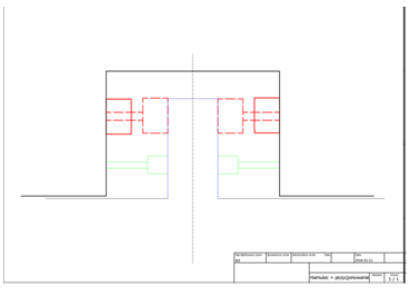
The ByPass station should also provide a technical service. The draft below presents approximate dimensions of each part. More precise scheme is attached.
ByPass station
In each ByPass station there will be 2 technicians working in shifts. They will be responsible for a technical control of the pods entering the ByPass, guiding the passengers in case of the emergency and for the first aid in life-threatening situations.
Another idea is to implement alternative pod monitoring systems in the stations. It will allow us to take control over the warning system in case of the main stations system failure.
Contact surface of the pods let them move freely on the magnetic cushions in the 3 degrees of freedom. ArxPax engines let us intelligently pilot the pods to the dock in order to drop the passengers.
A crane has to be installed in each station in order to have a possibility of moving a pod from the track onto a vehicle ready to land transport.
Additionally, the staff should be trained medically, and both first aid kit and AED should be supplied, in case of the most immediate medical emergencies, which could not wait until reaching the end station. This situation could especially occur in By-pass Tubes close to the end stations (far from the destiny stations).
D – Carriage
The carriage is used in case of pod’s emergency stop in the tube and inability to continue the ride. Its role is to push the pod to the next ByPass. The carriage is an autonomous unit, independent from external power supply.
The carriage consists of 4 main parts:
D1 – Steering system – unmanned vehicle controlled by a computer.
D2 – Levitation and propulsion systems – the carriage will be equipped in some additional levitation engines which will generate an extra force assisting the acceleration of the pod.
D3 – Power supply – electrical cells which will drive the levitation and steering systems.
D4 – Pod docking terminal – the carriage may be connected to the pod using the specially shaped terminal transmitting propulsion forces.
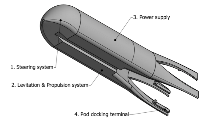
Carriage scheme
The carriage is not equipped with the turbine and the passengers’ deck. It reduces the mass and the energy required to maintain the pod’s levitation. The power excess may be used by installing greater number of MFA engines responsible for the levitation and propulsion.
In case of power grid failure and inability to move the pod out of the ByPass using the linear engine, the carriage, equipped with the autonomous propulsion system, pushes the pod up to the main track, at the same time helping it to reach the proper velocity for a given segment of the tube. Thanks to that the accelerated pod continues its ride and the carriage comes back to ByPass using the next exit.
Emergency propulsion
The complete propulsion failure is prevented by using modular composition of power and propulsion system. All batteries packs and engines are separate entities with separate wring and all other accompanying systems. Furthermore, the system is divided into subsystems, which are further divided into sub-subsystems. The subsystems are comprised of a pair of battery packs and a pair of engines, which are all interconnected. All the subsystems are connected to the subsystems of the corresponding level, which guarantees robustness of the system as a whole.
In case of compressor failure, which would create syringe effect in turns slowing the pod significantly. To prevent that, if rapid removal of the pod from the track would be needed, the linear engine is used to provide additional propulsion at the cost of efficient levitation. To enable that, the balls supporting the pod are ejected.
Finally, in case of the failure of both systems, however unlikely, special carriage, which is described in detail in by-pass chapter is used to haul the pod to the nearest by-pass.
Emergency suspension – spheres
To prevent pod’s collision with the track in case of failure of the magnetic propulsion system, a system of balls is employed. Balls are used instead of wheels as they have a number of advantages over conventional wheels. First and most important advantage is that they can move in any direction, which is impossible for uni-directional wheels. On the other hand, wheels, which can move in any direction as in shopping cart, would undergo high stresses and incur higher costs, as they have more complicated geometry. Additionally, normal wheels would be put under high dynamic stresses in bends as sketched in figure given below, which could lead to fatigue failure.
Forces on traditional wheel at bend
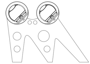
The balls are socketed and suspended from the bottom of the chassis. The sketch of the ball with the socket including ball bearings is given in the figure below. The suspension is used to minimize the effect of initial impact. These balls are located throughout the whole chassis to minimize the load on a single ball. Furthermore, they are normally hidden to streamline airflow beneath the pod and are rapidly ejected in case of failure of propulsion. What is more, the balls need to be hidden as the clearance between the track the bottom of the pod is too small. They are ejected by the means of CO2 micro explosions and strong pre-tensioned springs which are all mechanically connected to magnetic system. When magnetic system fails, the balls are automatically ejected, before the pod hits the ground. The balls are made of material elastic enough to efficiently dampen vibrations, while being hard enough not to deform during the impact or later operation. Also fatigue must be taken into account, as the balls will roll extremely fast. For these reasons, balls are made of high-grade carbon fibre coated in PTFE.
In order to successfully implement this solution one obstacle needs to be surmounted: the lubrication. As normal bearings are isolated from the environment, the dust cannot get inside the bearing. However here, the bearing is open, so the dust can easily penetrate the bearing and soon wear the ball and the bearings, which could lead to the failure of the system. Current solution to this problem is intensive lubrication system, which would consist of many jets, which would inject liquid (preferable some kind of oil) between bearing and ball, at the same time lubricating and cleaning the system.
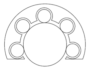
Socketed spheres
Emergency scenarios
Due to some emergencies that may occur during the travel, safety procedures were designed to support the system. The following emergency scenarios have been defined:
- Power outage (pod and tube)
If power outage occurs, there are batteries placed in separated anti-fire chambers with low pressure and low oxygen content. In case of batteries’ failure the pod, with a help of the trolley, will arrive to the ByPass (will be discussed below) to be repaired. - Tube depressurization
As tube depressurization may occur, the main control system constantly monitors the level of pressure in the tube. It either decreases the pod’s velocity and performs further control or in case of severe leak it leads the pod to the ByPass. - Pod depressurization
In case of a leak, pod is directed to a bypass for inspection while people may board additional pod which is in the bypass. During pressure drop, oxygen masks are available for passengers to ensure the breathing conditions and safety. - Fire
In case of a fire, each capsule has smoke detectors in both passengers’ and machine elements’ part. Every capsule has a fire extinguishing system on board. After sensing the smoke, each pod is moved to the nearest bypass tube or exit. When the smoke is detected in part with machine elements, the fire area is rapidly depressurized and repressurized. As a result of lack of oxygen, the fire is extinguished.
By-pass Tube
In case of a random event which implies a need for an instantaneous leaving the tube, we have created the ByPass. It is a mid-station. Located next to a freeway makes it possible to react quickly in case of a breakdown or in a life-threatening situation. When whole the system is broken the passengers may be transported on a freeway to the final destination.
The ByPass idea may be a base to creating new mid-stations which will be required after building another Hyperloop locations and further project development.
The ByPass description presented below is divided into following sections:
A – Exit
B – Air lock
C – Station
D – Carriage
Below, the detailed description of each part is presented:
A – Exit
In a situation demanding leaving the tube, the pod is being prepared to enter the ByPass station. It takes place in a special tunnel which segments are presented below.
- Exit scheme


- Overview of the ByPass exit
A1 – Directional tunnel.
A2 – Section preparing the pod to enter the ByPass. Pods are being separated so as to ensure the repeatability, universality and modularity – the tube is being divided into two. The rail comes out and the pod enters the ByPass.
A3 – Tubes separation. The leaving pod starts to move away from the primal path, entering the ByPass. Separating segments are 200 m long (it is due to the curvature of the rail).
A4- The track lowers its vertical position. This part will be up to 2 km long which will allow the pod to brake with 3G acceleration. The segment ends with the pressure chamber.
B – Air-lock
In order to equalize the pressure at the inside of the tunnel, the pod passes through the equalizing air-lock. It is located at all the entries and exits of each station. The pod should enter the air-lock with the maneuvering speed and then it should stop inside. After equalizing the pressure, the pod leaves the air-lock. It should be a one-stage air-lock, working in the range from 0.1 to 1 bars.
C – Station
The ByPass station should also provide a technical service. The draft below presents approximate dimensions of each part. More precise scheme is attached.

- ByPass station
D – Carriage
The carriage is used in case of pod’s emergency stop in the tube and inability to continue the ride. Its role is to push the pod to the next ByPass. The carriage is an autonomous unit, independent from external power supply.
The carriage consists of 4 main parts:
D1 – Steering system – unmanned vehicle controlled by a computer.
D2 – Levitation and propulsion systems – the carriage will be equipped in some additional levitation engines which will generate an extra force assisting the acceleration of the pod.
D3 – Power supply – electrical cells which will drive the levitation and steering systems.
D4 – Pod docking terminal – the carriage may be connected to the pod using the specially shaped terminal transmitting propulsion forces.

- Carriage scheme

Emergency propulsion
The complete propulsion failure is prevented by using modular composition of power and propulsion system. All batteries packs and engines are separate entities with separate wring and all other accompanying systems.
In case of compressor failure, which would create syringe effect in turns slowing the pod significantly. To prevent that, if rapid removal of the pod from the track would be needed, the linear engine is used to provide additional propulsion at the cost of efficient levitation.
Finally, in case of the failure of both systems, however unlikely, special carriage, which is described in detail in by-pass chapter is used to haul the pod to the nearest by-pass.
Emergency suspension – spheres
To prevent pod’s collision with the track in case of failure of the magnetic propulsion system, a system of balls is employed. Balls are used instead of wheels as they have a number of advantages over conventional wheels.
The balls are socketed and suspended from the bottom of the chassis. The sketch of the ball with the socket including ball bearings is given in the Fig. X1. The suspension is used to minimize the effect of initial impact. These balls are located throughout the whole chassis to minimize the load on a single ball. Furthermore, they are normally hidden to streamline airflow beneath the pod and are rapidly ejected in case of failure of propulsion.
- Socketed spheres
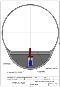
Track construction
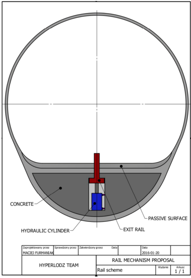
Tube
Tube consists of passive surface, concrete base and rail. Passive surface is made of aluminum or other passive conductive material (more in chapter devoted to levitation system). Concrete base allows to transfer vibrations and loads to pylons and provides stability. Cross section of the tube is presented in Fig. X2.
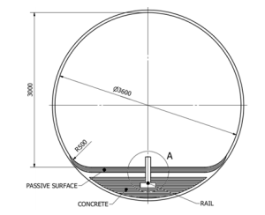
- Tube cross section

Tube is supported by pylons. Futuristic pylons design suits to the overall Hyperloop design. (Fig. X4)
- Tube supported by pylons
The main component of the track is the rail, which provides propulsion, breaking and positioning. It is located in the center of the track as in the figure below. All functions are described in detail below.

- Sketch of the rail with accompanying PBP system
The propulsion is provided by linear motors, which are mounted on rail in the parts on the track, in which it is necessary – near the by-passes and at the bends as well as at the beginning and the end of the track. The stator is located on the rail, while the rotor is a part of the pod. This propulsion system is also used for breaking. The brakes are regenerative – they recover energy when the pod is decelerating, which drives the power consumption and costs down.
Positioning
If the pod approached the bend with inadequate velocity (either too high or too low), it would normally deviate from the middle position causing vibration and disturbing the airflow around the pod, which might in turn cause local sonic booms. To prevent that, a system of positioning bearings located in the chassis of the pod and touching sides of the rail is used. These bearings are not loaded and provide only slight position adjustments.
By-pass approach
As mentioned before, by-pass stations are used in case of emergency. If such situation arises the pod is guided to the by-passes by rails, which emerge from the track as in the Fig. 29. This facilitates the removal of pod from the track and ensures mechanically that the pod will enter the by-pass.
- By-pass approach

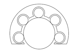
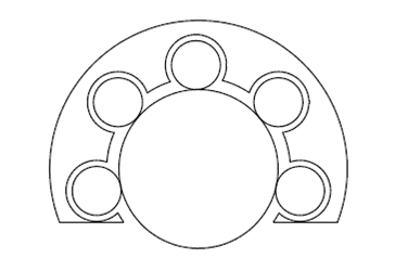
Bends
One should understand that the Hyperloop pod velocity depends i.a. on the tube shape. The track (tube) shape and pod velocity is determined by characteristics of the terrain (environment) on which the track is built.
When the pod will travel in bended tube with high velocity, passengers will experience huge centrifugal force. It was decided to change centrifugal force into vector component that is balanced by the lift force of hover engines (fig. X6). Such a solution is possible by a proper shape of the track.

- Transferring centrifugal force into component balanced by Hover Engines
The track is tilted at turns so the resultant force coming from centrifugal force and the force of gravity is perpendicular to the truck surface. This method eliminates discomfort of being pushed to the side of a seat. Instead, passengers are pushed into seats, which does not cause discomfort. However, to avoid too big g-forces acting on passengers, the bend cannot be sudden. The turn has to start early and the track radius should shorten from infinity to critical radius in such a manner so the g-force value does not exceed 1G. In order to increase stability and durability of tube construction, pylons should be tilted as well to be perpendicular to the hover surface.

- Different radii of a bend
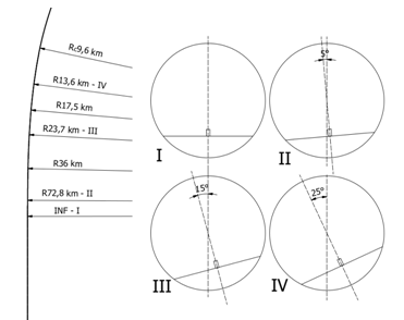
- Sketches of tube supported by pylons on a bend

But g-forces are not determined only by shape of the track. Velocity has also a great influence. For that reason, the pod will slow down before taking turns. Pod velocity in normal conditions (not during failure of any subsystem) is controlled mainly by linear motors, so the velocity values in different points of the track are repeatable for each pod.
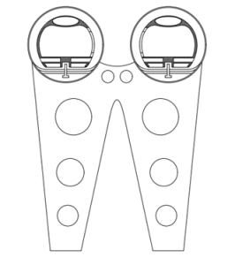
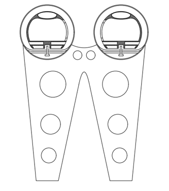
Station
- Station overview

The station would be a two-story building, with the business and entertainment zone on the ground level and the docking bay and capsule service on the first floor. Most of the upper deck would be the Rink with six docking bays on either sides of the room, each accommodating two capsules at once. The rest of the floor would be taken up by the service center, where the capsules would be attended to, with their batteries changed and any faults repaired.
Interior design and ergonomy
Seats
In our design of the pod interior we decided to use only rear facing seats. Main reason for such a configuration is safety at the moment of sudden deceleration in case of emergency braking. In forward-facing seats, the passenger is propelled into a very narrow lap belt. This causes the body to jack-knife – the torso and limbs fly forward while the hips stay back. In seats facing backwards the passenger is pushed into the back of the seat, and the force is spread more evenly. The seat would support the head, torso, hips and limbs and significantly reduce the potential for injury. All the positive aspects of sitting in opposite direction to the vehicle speed comes from the distribution of the load along the human body.
However, Many people around the world has a serious problem with seating backwards, because of the view from the window. From their relative position the landscape “moves” in abnormal direction – they are just not accustomed for such a situation, as they are sitting in a face-forward manner for the whole life. This problem will be resolved by displaying the typical Californian landscape on the bent screens mounted on the sides of the capsule. This installation provides a number of advantages:
- Passengers will not sense a claustrophobic effect of travelling in a capsule with very small space inside.
- Landscape projected on the screen will be moving with the maximal velocity of the range of 100-200 km/h. This solution enables passengers to really observe the details of projection – displaying the scenery with the velocity equal to 1000 km/h will cause only the blurred view able to cause nauseating effects.
- Visualizations on the screen will also be displayed in the reversed manner – passengers, thanks to this solution, will feel like they travel normally and seat in forward-facing configuration.
Entertainment
As far as the personal satisfaction of the passengers is concerned, we decided to provide them as many entertainment options as possible during the travel. Our solution is to install 9’’ multifunctional screens at the back of preceding seats with a keyboard (equipped with a touchpad instead of a mouse) that can be pulled out to navigate.
We want to provide passengers wide range of activities like music, films, multiplayer games with other passengers, digital coloring books for children, audio and ebooks.
Air exchange and ventilation
The pressure inside the pod will be kept at the atmospheric level as the whole construction will be sealed. Due to the lack of air exchange, the air inside the capsule should be oxidized throughout the trip to ensure the comfort of breathing. At the same time, the excess of carbon dioxide should be removed.
Control, communication and positioning systems
Diagnosis network and control system.
The onboard communication network in HyperLodz Pod is based on the CANOpen technology and mainly consists of two major parts: onboard diagnosis network and onboard control network.
The diagnosis network in HyperLodz pod is a two-layer architecture including Capsule Network based on CANbus and Train Network based on Ethernet.
The control system of HyperLodz pod takes charge of the transmission and performance of control orders and safe status signals. It is the “Nerve Centre” of capsule safe traveling. In Capsule control system doors and air conditioning, as well as the safety power supply system, braking system, passenger message display system, broadcasting system, smoke sensor, and other equipment, are controlled by the independent controllers.
Pod navigation system
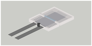
Each pod gains information about its actual position based on linear encoder. A sensor is paired with a series of fluorescent stickers that encodes position in tube. The sensor reads the scale in order to convert encoded position into a digital signal which can be decoded into a position. Motion is determined by change in tube position over passing time. This optical linear encoders base on holographic principles are enough accuracy of the standard styles of encoders, and the most commonly used in industrial automation applications.
Communication between pods
The communication between pods and external navigation system uses wireless network (Wi-Fi, Bluetooth) and cables (optical fibers). Buses are placed along the track and are connected to the wireless emitters
The capsule tracking system collects information about localization, speed and condition of the capsule. It computes and checks if there is a risk of collision. In case of possible accident the system calculates the best option and immediately transmits solution to the pods.
Mass of the pod and consumed power
Mass estimation
The mass, calculated for every subsystem can be seen in the table below.
| Element | Mass [kg] |
| Passengers | 4500 |
| Luggage | 700 |
| Compressor and motor | 1500 |
| Fuselage and structure | 4500 |
| Entertainment | 750 |
| Air systems | 150 |
| Linear motor rotor | 1000 |
| Magnetic engines | 3655 |
| Batteries | 7000 |
| Interior elements | 1700 |
| Total mass | 25455 |
11.2 Power consumption
Estimated power consumption can be seen in the table below.
| Element | Power [W] |
| Compressor and motor | 500000 |
| Entertainment | 4000 |
| Air systems | 20000 |
| Magnetic engines | 2526300 |
| Total power | 3050300 |
The main elements influencing the power consumption are magnetic engines for levitation. The value of power estimated in this case is for the assumption that 70 W are needed to lift 1 kg of mass. ARX PAX indicated that they managed to obtain a motor with efficiency of 33 W per 1 kg of mass. The more detailed description of magnetic motors technology and assumptions made can be found in Levitation section.
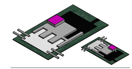
Batteries used in the pod
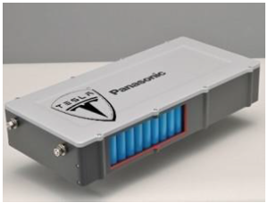
- Pack of batteries

Li-Ion Panasonic 18650 Battery having the following characteristics:
- nominal Voltage = 3.6V,
- rated capacity min. C=2950 mAh , typ. 3070mAh,
- size: 18.5 x 65.3,
- weight: 47.5 g,
- energy density: 245 Wh/kg.
We will use batteries from Tesla Model S for logistical and financial reasons rather than for performance. This means that Panasonic, is currently producing these cells in fully depreciated
factories and have already started optimizing the manufacturing costs. . They are going to be much cheaper than buying large custom batteries. From Empirical Research Methods as battery size increases, its capacity, volume, and weight all increase (large objects have higher ratio of volume/surface-area than small ones do) but several reasons may be found why small batteries are better than bigger ones.
Heat profile
Heat exchange in the pod surrounded by air of very low pressure and density is very problematic. To the advantage may come the fact, that the pod is travelling with a very high speed, and that the constant depressurization of the air in the tunnel causes constant temperature decrease.
In the same time various subsystems of the pod generate big amounts of heat. The most significant are the compressor, electric motor and batteries. Heat generated by the levitation engines is told not to be of significant value, additionally engines are immersed in the flow of air.
According to our CFD simulation, the temperature of the flow around the pod does not change. Taking advantage of this phenomenon and of the fact that the air in the tunnel is being constantly depressurized, what is equivalent with decreasing its temperature, we use the flow of this low temperature to cool the pod.
From all the systems heat pipes with either active or passive heat flow should be used with connection to the outer layer of the fuselage. From the air duct heat should be evacuated through the top boundary of the duct, directly to the air flow. In this case structural function should be borne by the lower wall of the air duct, which should be additionally isolated from passenger compartment.
Discussion and conclusions
The project delivers preliminary design of a pod for innovative mode of transportation „Hyperloop”. The pod is designed to operate at transonic speed in custom-built track to connect urban hubs at medium distances (between 500 and 1000 km). In order to decrease power consumption and costs, the pods move in extremely low pressures. This decreases energy losses due to aerodynamic drag. The team’s solution focuses on robust, comprehensive and coherent design proving the feasibility of concept. The emphasis is put on safety, which is of paramount importance, as it should encourage people to use new, innovative and high-speed mode of transportation.
The members of our team were mainly focused on developing concepts and innovative applications for the existing technologies which suit the idea of Hyperloop and gives new and fresh insight into the subject.
One of the main advantages of the design is the comprehensive safety system, which takes into account many emergency scenarios and provides solution to most of them. The intentional redundancy of many systems increases safety and reliability of the pod. Solid design of aerodynamics and magnetism part of the pod provides good overview of technologies used and feasibility of their implementation.
Additionally, the aerodynamics of the pod, while solid, should definitely be improved upon to further reduce drag and improve other characteristics. Iterative optimization should be employed here until satisfying solution is achieved – that is no significant improvement is obtained with consecutive iterations.
There are other areas, which should be explored, the most important of which is probably dynamic analysis to investigate the magnitude of vibrations and its effect on the pod, track and passengers. Firstly, prohibited frequencies for all main parts should be established to ensure that resonance is not an issue. Then, dynamic response of the pod due to airflow and contact with track at various velocities should be established. If the examined vibrations exceed magnitudes safe for humans, additional optimization would be required.
What is more, few basic features are only roughly estimated, including number and characteristic of engines. The latter is caused by the lack of access to detailed description of the engines. This would also affect the mass of the pod, which is as well only roughly estimated.
Finally, thermal profiles of the main parts, including compressor, chassis and body should be determined to ensure that excessive temperatures are not an issue and no significant thermal deformation takes place.
References
(1) http://www.edubilla.com/